|
Quality and Autogard are
synonymous with overload protection. The company's reputation for high
quality products is derived from over 35 years of design innovation and
production. Autogard products are manufactured to meet ISO 9001 using
the latest machine tools and high quality materials.
The Autogard Series 820 has been designed to
meet the emerging need for a high torque, high and low speed Torque
Limiter.
The Torque Limiter is designed using a modular
principle. The trip torque setting can be set to virtually any value. It
is dependant upon the radius at which the modules are located and the
number of modules used.
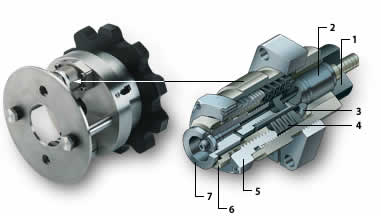
A hardened seat (1) is built into one half of
the Torque Limiter. The module unit is then located into the opposing
flange in such a way that the torque is transmitted between the plunger
(2) and the hardened seat. This produces an end thrust in the plunger in
proportion to the applied torque. This force is resisted by a ring of
segments (3) trapped between a flat surface and a conical washer loaded
by disc springs (4). When the axial force reaches a level greater than
the reaction force through the spring mechanism, the plunger will
retract forcing the segments up the plunger slope and allowing the
plunger to disengage from the hardened seat. The Torque Limiter is now
allowed to run free.
The trip torque is externally adjusted and is
achieved by turning the adjustment nut (5) to increase or decrease the
spring pressure. Resetting is accomplished by simply aligning the two
halves, positioning the plunger over the hardened seat, and tapping the
reset pin (7) with a soft hammer. Automatic reset versions are also
available.
The modular Torque Limiter may incorporate an
optional limit switch plate, which moves on trip and can operate a
switch to stop the drive.
|
|
|
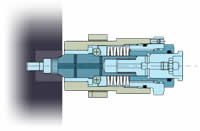
| Engaged |
Disengaged |
|
Features
and Benefits
|
| |
Accurate
and consistent torque setting ensuring reliable and repeatable
torque overload protection. |
| |
Instant
and complete disengagement of the driving and driven inertias
ensuring optimum protection. |
| |
Trip
torque can be adjusted easily without removing the modules
from the Torque Limiter. |
| |
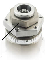
Vernier
scales are provided on each module allowing for accurate
setting of the modules. |
| |
In the
event of an overload, standard limit switches or proximity
sensors can provide automatic motor shutdown. |
| |
The
module can be quickly and easily reset. Manual or automatic
resets are available. |
| |
Manual
disengagement allows for the unit to be disconnected for
maintenance purposes. |
| |
Integral
grease fitting allows for periodic lubrication of the unit
without removing it from the drive line. |
| |
Wide range of
mounting configurations ensures the right solution for any
problem. |
| |
Drop-out center
section allows the Torque Limiter to be removed from the drive
line without moving the equipment. |
 |
The vernier allows for accurate and
consistent adjustment of each module. |
|
|
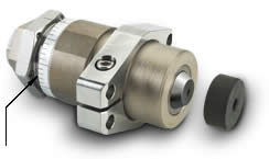
Manual disengagement nut (6) can be used to disengage the
module, without affecting the torque setting. By simply rotating
the sleeve back to its original position and hitting the reset
pin with a soft hammer, the unit is once again fully operational |
Series 820 Torque
Limiter Selection
|
Method
|
| Data
required for Torque Limiter Selection. |
| |
Application
details (for service factors). |
| |
Kilowatt
and rpm of the driver. |
| |
Shaft
details of the driving and driven equipment. |
|
| (1) |
Determine the nominal torque (Nm)
Torque (Nm) = Kilowatt (Kw) x 9550 / rpm
Consideration should then be given to start torque or other
special circumstances depending on the position chosen in the
drive system. Choose a set torque with a suitable margin over
nominal. Select the Torque Limiter which has a higher torque
rating. For 820 Type 1 check pin coupling selection.
|
| (2) |
Check the Limiting Conditions:
|
| (a) |
Check hub
bore capacity and speed rating. |
| (b) |
Check the
Torque Limiter dimensions such as the overall length and
outside diameter. |
| (3) |
Select and
specify the appropriate drive medium or coupling. |
| All Autogard Series
820 units may be supplied from the factory at a pre-set torque
and with the required drive medium assembled to the unit. |
|
Model 820
Type 1 - Pin Coupling Selection Method
|
| When
selecting a Model 820 Type 1, the customer needs to confirm
that the coupling is suitable for the continuous torque taking
into account the duty in which the unit will be used. |
| (1) |
Determine the nominal torque
Torque (Nm) = Kilowatt (Kw) x 9550 / rpm.
|
| (2) |
Select the appropriate service factor
fD as shown in Table 1 taking into account hours of operation
per day and the prime mover used.
|
| (3) |
From Table 2 select the factor for
the frequency of starts per hour (fS).
|
| (4) |
Determine selection torque.
Selection Torque (Nm) = nominal torque x fD x fS.
|
| (5) |
Check to ensure that the couplings
nominal torque rating exceeds the selection torque. If is does
not, select the next larger torque limiter which meets this
criterion.
|
_______________________________________________
|
Table
1 - Pin Coupling Service Factor (fD) (820 - Type 1
only)
|
| |
Driven
machinery characteristics |
Prime
mover
(Drive input) |
Duration
Service
Hours/day |
Steady
Load |
Medium
impulsive |
Highly
impulsive |
Electric,
Air,
Hydraulic Motors
Steam Turbines
(Steady input) |
Intermittent
3 hrs/day max
3 - 10
over 10 |
0.90
1.00
1.25 |
1.00
1.25
1.50 |
1.50
1.75
2.00 |
Multi-cylinder
I.C. Engine
(Medium Impulsive input) |
Intermittent
3 hrs/day max
3 - 10
over 10 |
1.00
1.25
1.50 |
1.25
1.50
1.75 |
1.75
2.00
2.25 |
Single-cylinder
I.C. engine
(Highly impulsive
input) |
Intermittent
3 hrs/day max
3 - 10
over 10 |
1.25
1.50
1.75 |
1.50
1.75
2.00 |
2.00
2.25
2.50 |
|
_______________________________________________
|
Table 2 -
Pin Coupling Service Factor (fS) (820 Type 1 only)
|
| No.
of Starts per Hour |
0
- 1 |
1
- 30 |
30
- 60 |
60
+ |
| Factor |
1.00 |
1.20 |
1.30 |
1.50 |
|
_______________________________________________
| Notes |
| |
Service
factors provided are for reference only. Customer experience
may dictate the selection of different Service Factors. |
| |
For
applications with excessive vibration, contact Ohio Belting |
| |
Rotating
Equipment must be provided with suitable guarding or injury
may result. |
_______________________________________________
| Ordering
the 820 Series Torque Limiter |
|
When
ordering please provide the following designation
Model & Size / Type / S1 Bore / S2 Bore
Standard bore tolerance = H8 + normal fit key.
Example:
820 - 3L / 2 / S1 - 110 / S2 - 130
Refers to a Model 820 size 3L Type 2 torque limiter
S1 Bore = 110 mm S2 Bore = 130 mm
Also specify setting torque if required.
|
|
|
