| Quality and Autogard are
synonymous with overload protection. The companys reputation for high
quality products is derived from over 35 years of design innovation and
production. Autogard products are manufactured to meet ISO 9001 using
the latest machine tools and high quality materials.
The Series 400 has been designed to meet the
emerging need for a high and low speed, free wheeling Torque Limiter.
The Series 400 differs from previous ball detent designs by using two
sets of balls on concentric pitch circles.
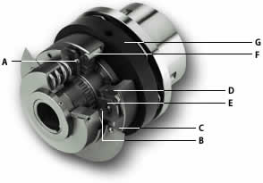
In the normal drive condition, torque is transmitted through the drive
balls A. The inner strut balls B are designed to carry no
load during this time.
Disengagement on
overload:
When an overload condition occurs, the drive
balls roll out of their seats forcing the slide plate C and drive
plate D apart. The cage plate E, strut balls and drive balls
all rotate until the cage plate hits a stop located in the slide plate.
At this point the spring pressure has been transferred from the drive
balls to the strut balls. The strut balls prevent the drive balls from
re-engaging the drive plate. The coupling or driven media attached to
adapter G is now completely free to rotate. Although the Series
400 has been designed to run freely after disengagement, it is
recommended that a shut-down switch is incorporated to avoid wear.
Re-engagement:
Re-engagement occurs when either the driving
side is reversed, or the driven side is advanced. Pawl F engages
the cage plate E and rotates it until the drive balls are
re-seated. Resetting must be done at low speed to permit the engaging
mechanism to function properly in either direction and to prevent
potential damage.
The resetting can be done manually or automatically by slowly inching
the motor in reverse.
The Series 400 comes standard as a Rapid Reset (RR) style Torque
Limiter. This gives the following maximum angles of rotation to
re-engage:
|
Size
|
Max rotation
to re-set
|
|
1
|
60°
|
|
2
|
67.5°
|
|
3
|
30°
|
|
4
|
30°
|
|
5
|
30°
|
|
6
|
25.7°
|
|
Synchronous Reset (SR) designs are also
available and must be specified at the time of ordering. These reset in
a constant angular position.
|

|
| Multiple
coil springs provide improved adjustment |
|
Multiple
coil springs provide improved serviceability |
__________________________________________
|
Features
and Benefits
|
| |
Proven
design with thousands of units successfully in operation. |
| |
Accurate
torque limitation prevents costly down time. |
| |
Standard
designs can accommodate large torque ranges. |
| |
Instantaneous
disengagement protects equipment from damaging inertias. |
| |
Bi-direction
protection. |
| |
Series
400 is designed to operate at High or Low speeds. |
| |
Automatic
or manual re-engagement by reversing the unit. |
| |
Series 400 is
offered in a large number of styles ensuring
the right solution is available for all applications.
e.g. |
| - Timing, HTD
& V-Belt drives |
| - Chain and
sprocket drives |
| - Gear drives |
| - Flexible or
rigid couplings |
| - Flywheel or
large gear mounts etc. |
|
| |
Springs
can be inspected and changed without removing the clutch from
the drive train. |
____________________________________________
| Selection |
| Data
required for torque limiter selection. |
| |
Kilowatt
or Horsepower and rpm of the driver. |
| |
Shaft
details of the driving and driven equipment. |
________________________________________
| (1) Calculate
the nominal torque: |
| Torque (Nm) =
Kilowatt (Kw) x 9550 / rpm or |
| Torque (lbf-ins)
= Horsepower (HP) x 63025 / rpm |
| Consideration
should then be given to start torque or other special
circumstances depending on the position chosen in the
drive system. Choose a set torque with a suitable
margin over nominal. Select the torque limiter which
has a higher torque rating. |
| (2) |
Check limiting
conditions: |
| (a) |
Check hub bore
capacity |
| (b) |
Check the
torque limiter dimensions such as the overall length
and outside diameter. |
| (3) |
Select and
specify the appropriate drive medium or coupling. |
| All Autogard
Series 400 units may be supplied from the factory at a
pre-set torque and with the required drive medium
assembled to the unit. |
|
______________________________________
| Ordering
the 400 Series Torque Limiter |
When
ordering please provide the following designation:
Model & Type / Size / Feature / S1 Bore / S2
Bore
Feature:
RR Rapid Reset (standard)
SR Synchronous Reset (optional)
S1 Bore & S2 Bore Please specify metric or
imperial.
Standard bore tolerance = H8 + normal Fit key
Example:
402 / 3 / SR / S1 40 mm
Refers to a type 402 size 3 torque limiter designed
for synchronous reset.
Bore S1 = 40 mm.
Also specify
Torque setting or torque range required
Pulley or sprocket details where required
|
|
|
