| Quality and
Autogard are synonymous with overload protection. The companys
reputation for high quality products is derived from over 35 years of
design innovation and production. Autogard products are manufactured to
meet ISO 9001 using the latest machine tools and high quality materials.
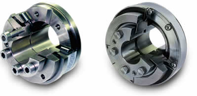
Autogard backlash-free
safety couplings work as spring-loaded positive couplings. The special
roller or ball guides guarantee a totally backlash-free transmission of
the torque in both directions of rotation.
The couplings are
therefore especially suitable for use in speed and direction controlled
drives in conjunction with a closed control loop.
Uniform loading of the rollers and balls guarantees high system
stiffness, which is important especially for modern servo drives.
The roller or ball
guides simultaneously guarantee high reliability and switching
frequencies when used with high dynamic servo drives.
 |
Cylindrical
roller Locking Element for low, medium and high
dynamic loads
Suitable for types
1,2,3,5,6 |
|
 |
Ball
style Locking Element for low and medium dynamic loads
Suitable for types
7, 8, 9, 10 |
|
________________________________________
| In the event of an overload
the rollers or balls move out of the guides (see figures 1 and
2). This results in an axial movement, which activates a
proximity switch or limit switch that immediately makes
contact to switch off the drive. To avoid damage to the safety
coupling, the drive must be switched off immediately after an
overload. Autogard backlash-free safety couplings were
developed for especially dynamic drives operated under
constantly changing directions of rotation and under high
acceleration. |
 |
Figure
1
Roller principle |
Figure
2
Ball principle |
|
|
The safety
couplings work exclusively with specially selected disk springs with a
pronounced digressive characteristic (see figures 3 and 4). This advantage
guarantees shortest switching times (2 4 msec) and a low residual
torque, less than 5% in a disengaged state. The coupling disengages
immediately when the cut-out torque is exceeded.
Figure 3
_________________________________________________
 |
|
Figure 4
|
|
The
torque drops immediately to a small residual value, typically 2
to 5%. The switching work required of our couplings corresponds
to only a fraction of that of conventional safety couplings with
progressive characteristic (see figure 3). This is a decisive
advantage because even ultra-short surges in speed are rendered
harmless by the safety coupling. |
Adjustment of the
cut-out torque:
Autogard backlash-free safety couplings are
delivered with set cut-out torque. There are two possibilities for this,
namely:
1) The user / operator names the cut-out torque in his order.
2) The coupling is set on the lowest cut-out torque in its torque range.
Figure 5 shows the spring travel we use for our
safety couplings.
Point A stands for the highest spring force = highest cut-out torque.
Point B stands for the lowest spring force = lowest cut-out torque.
Note!
The spring travel corresponds approximately to three-quarters of a
revolution of the set collar. Every required cut-out torque is
progressively adjustable.
|
|
|
Figure 5
|
|
Due to the
digressive characteristic, the cut-out torque is reduced when
the set collar is turned in a clockwise direction (towards min.)
and raised when turned in an anti-clockwise direction (towards
max.).
Note! The set collar may only be turned between min. and max.! |
Figure 6 |
